What is a PIC Microcontroller
Introduction to PIC Microcontrollers
PIC stands for Peripheral Interface Controller, A PIC microcontroller is a small computer on a single integrated circuit designed to control a specific task. It contains input/output ports, RAM Random Access Memory, ROM Read Only Memory and a CPU (Central Processing Unit) on a chip. PIC microcontrollers are frequently used in embedded systems such as consumer electronics, industrial-level applications, and automotive electronics. They are known for their low power consumption, high performance, and ease of use.
Brief history of its development
General Instruments first introduced PIC microcontrollers in the 1970s. However, in the early 1990s, Microchip Technology acquired its rights and started producing it commercially. Since then, PIC microcontrollers have become one of the most popular worldwide, with a wide range of applications in various industries.
Importance of PIC Microcontrollers in modern technology
PIC Microcontrollers play a crucial role in modern technology, powering many embedded systems in the automotive, industrial, and consumer electronics industries. Their low power consumption, high performance, and ease of use make them a popular choice for developers. Thanks to their widespread use and versatility, PIC Microcontrollers will likely continue shaping the future of technology for years to come.
Features of PIC Microcontroller
Overview of PIC Microcontroller architecture
The PIC Microcontroller architecture is designed to be efficient and flexible, with various features that make it suitable for various applications. These features include multiple communication interfaces, on-chip memory, and advanced peripherals such as timers, ADCs, and PWM modules. The architecture also supports various programming languages and development tools, making it easy for developers to create custom applications. Overall, the features of the PIC Microcontroller make it a powerful and versatile tool for modern technology.
Different types of PIC Microcontrollers
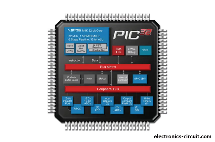
There are several different types of PIC Microcontrollers available, each with its own unique features and capabilities. The most popular types include the PIC16, PIC18, and PIC32 families. These microcontrollers vary in processing power, memory capacity, and communication interfaces, allowing developers to choose the best option for their specific project needs. There are also specialized PIC Microcontrollers available for specific applications, such as motor control or LED lighting. With such a wide range of options available.
Memory and speed capabilities
The memory and speed capabilities of PIC Microcontrollers are also impressive. They can range from a few hundred bytes of RAM to several kilobytes and from a few hundred instructions per second to several million. This allows for efficient and effective data processing and instructions, making them ideal for various applications. Overall, the features, capabilities, and versatility make the PIC Microcontroller a valuable tool in modern technology.
Architecture of PIC Microcontroller
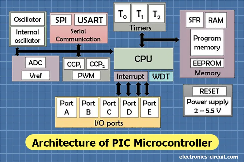
The PIC microcontroller's architecture contains the CPU, memory configuration, I/O ports, timers and counters, A/D converter, interrupts, oscillator, serial communication, and CCP module, all covered in more detail below.
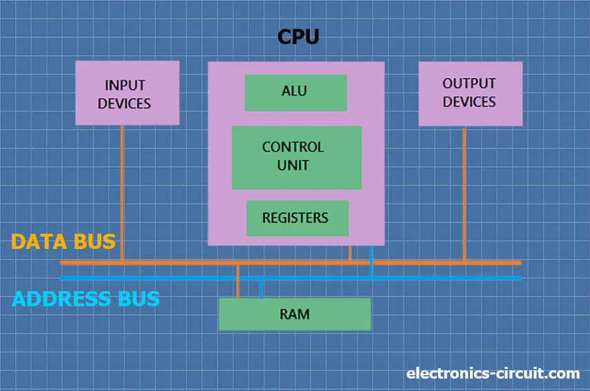
CPU (Central Processing Unit)
The PIC microcontroller's CPU parts are the ALU, CU, MU, and accumulator. The arithmetic logic unit is primarily used for mathematical operations and logical judgments. The instructions are processed and then stored in memory. The control unit, which is connected to the CPU, is used to control both internal and external peripherals, and the accumulator is used to store the outcomes and carry out further processing.
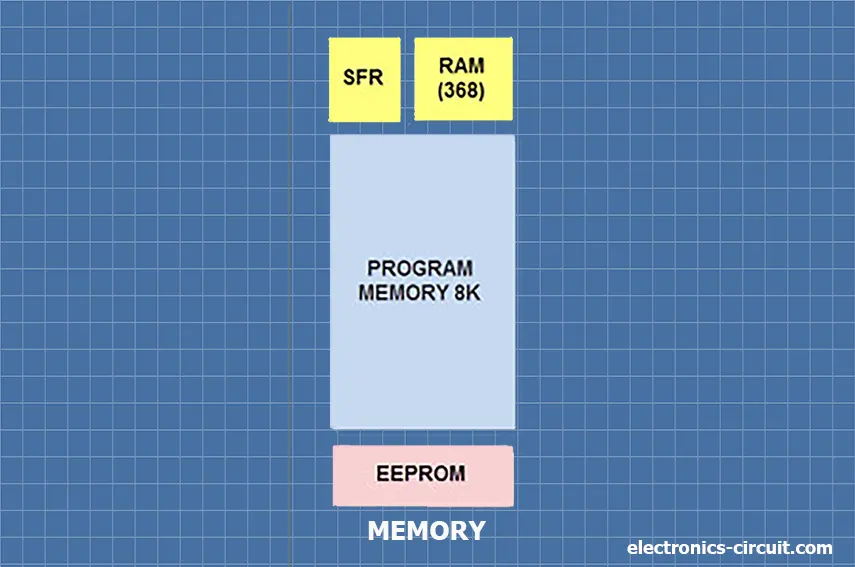
Memory Organization
In the architecture of PIC microcontroller, ROM (read-only memory), RAM (random access memory), and STACK are the main memory modules.
Read Only Memory (ROM)
A stable memory that is used to store data permanently is read-only memory. In the PIC microcontroller architecture, the ROM stores the instructions or program, and the microcontroller executes them as directed by the program. The ROM is also known as program memory. It is where users write programs for microcontrollers, save them permanently, and then wait for the CPU to execute them. The performance of the microcontrollers is influenced by the CPU's execution of the instruction.
Random Access Memory (RAM)
Data is temporarily stored in the registers of RAM, an unstable memory. The RAM memory is divided into two banks, and each bank has a large number of registers. Special Function Registers (SFR) and General Purpose Registers (GPR) are the two categories into which the RAM registers fall.
According to their name, these registers are only used for general purposes. For instance, we could use the PIC microcontroller to multiply two numbers. Registers are typically used to multiply numbers and store the results in other registers. Because the CPU can easily access the data in the registers, they serve no special purpose.
As their name suggests, SFR registers are only used for special purposes. These registers can only be used for the tasks given to them; they will not function normally. These registers display the program's operation or status; for instance, if the STATUS register cannot be used to store the data. Therefore, the user cannot change the SFR's function; the function is set by the retailer when the device is made.
Flash Memory
The programme can be read, written to, and erased thousands of times in flash memory, also a programmable read-only memory (PROM). The PIC microcontroller typically uses this kind of ROM.
Electrically Erasable Programmable Read Only Memory (EEPROM)
In a normal ROM, you can only write code once. You can only use the microcontroller once. But in an EEPROM, the ROM can be written more than once.
Stack
The PIC microcontroller must first execute the interrupt and the current process address when an interrupt occurs. Then, it is placed on the stack for execution. After an interrupt has been processed, the microcontroller will execute the process at its stored location from the stack.
BUS
Information can be sent and received between various peripherals using a BUS. The two main categories are "data bus" and "address bus."
Data Bus: It is only used to send and receive data.
Address Bus: The address bus sends the memory address from the hardware to the CPU. I/O pins are used to connect to external peripherals. UART and USART are serial transmission protocols used to connect to serial devices like GSM, GPS, Bluetooth, IR, etc.
I/O Ports
The PIC16 series has five ports: Port A, Port B, Port C, Port D, and Port E.
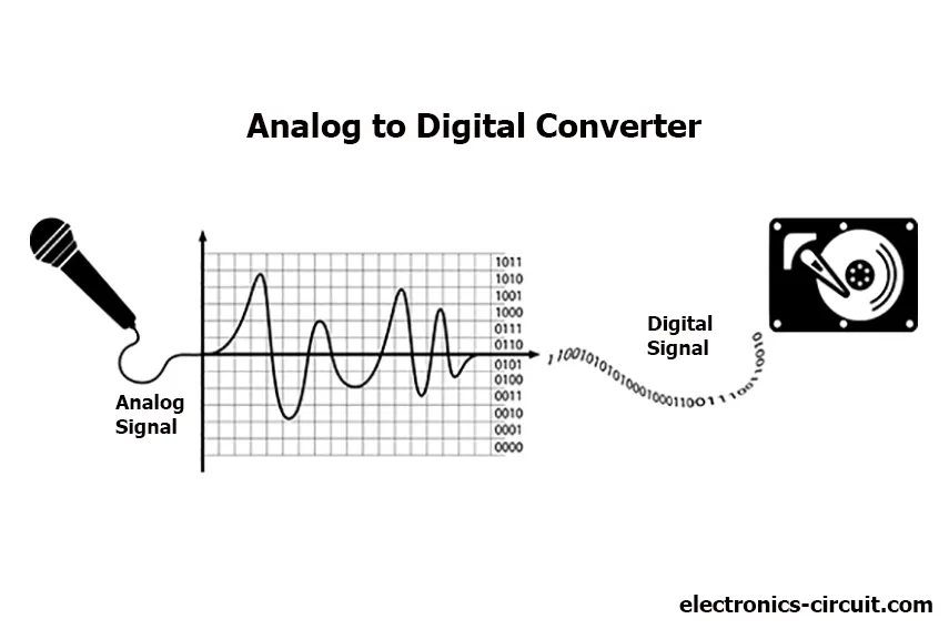
A/D Converters
The primary function of this analog-to-digital converter is to perform that very conversion from analogue voltage to digital voltage. The PIC microcontroller's A/D module has five inputs for devices with 28 pins and eight inputs for devices with 40 pins. ADCON0 and ADCON1 are special registers that regulate the A/D conversion process. Register ADRESH stores the converter's upper bits while registering ADRESL stores the converter's lower bits. An analogue reference voltage of 5V is needed for this procedure.
Interrupts
The PIC microcontroller has 20 internal interrupts and three external interrupt sources connected to devices like ADC, USART, Timers, etc.
Timers/ Counters
There are four timers/counters in a PIC microcontroller, one of which is an 8-bit timer. The other three timers can operate in either 8-bit or 16-bit mode. Timers are used to generate specific activities, including establishing fixed intervals between two processes.
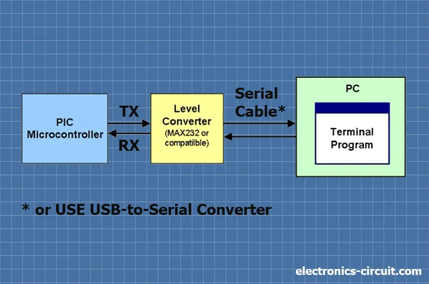
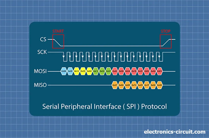
Serial Communication
Serial communication is a way to send data over a communication route one bit at a time in a certain order.
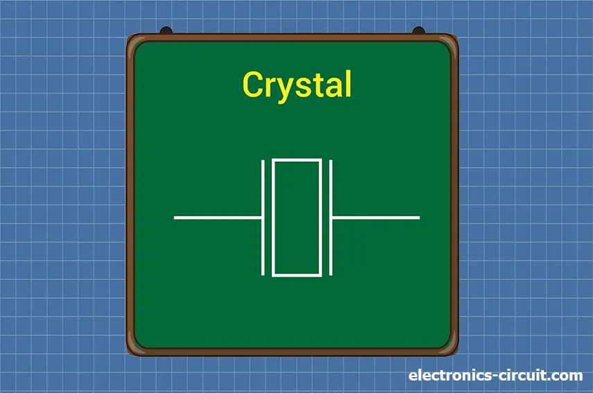
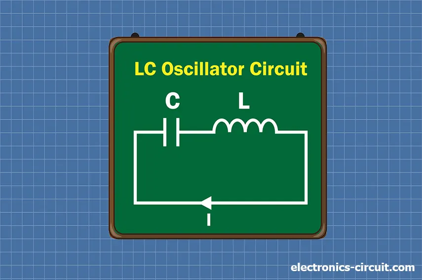
Oscillators
Timing is made with the help of oscillators. External oscillators, such as RC or crystal oscillators, are part of a Pic microcontroller. Between the two oscillator pins is where the crystal oscillator is connected. Every pin is linked to the value of the capacitor, which controls how the oscillator works. There are three modes: crystal, high-speed, and low-power. In RC oscillators, the clock frequency is determined by the resistor and capacitor values. The clock frequency can be anywhere from 30KHz to 4MHz.
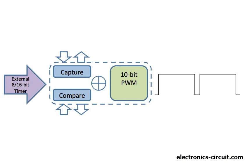
CCP module
"CCP module" is an abbreviation for "capture/compare/PWM". It works in three ways: capture mode, compare mode, and PWM mode.
Applications of PIC Microcontroller
Overall, the PIC Microcontroller has various applications in various industries due to its versatility and capabilities. It has become an essential component of modern technology.
Conclusion
The PIC Microcontroller is a versatile and valuable tool in modern technology, with a wide range of applications in consumer electronics, industrial automation, and medical devices. Programming a PIC Microcontroller involves understanding programming languages and following specific steps with resources available for learning. While the PIC Microcontroller has cost, size, and power consumption advantages, it also has programming complexity and memory limitations. The future of PIC Microcontrollers includes emerging trends and possible future applications with an impact.


