Arduino CAN-BUS Shield V2
Brief Explanation of CAN BUS Technology
CAN bus technology is a communication protocol commonly used in the automotive industry for exchanging data between electronic control units (ECUs). The real-time transmission of information such as wheel speed, engine speed and other sensor data is crucial for the proper functioning of modern vehicles. CAN bus technology has also applications in other industries, such as industrial automation, aerospace, and medical equipment.
CAN BUS Arduino Shield V2.0
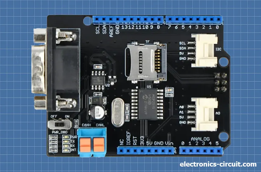
The ARDUINO CAN BUS Shield V2.0 is a powerful tool that allows for easy integration of the CAN bus technology into Arduino projects. It features a high-speed SPI interface, on-board voltage regulator, and support for both CAN 2.0A and CAN 2.0B protocols. Additionally, it has a built-in SD card slot for data logging and supports up to 110 nodes on the network. With this CAN-BUS Shield, you can easily add CAN-BUS capability to your Arduino/Seeeduino. It features a reliable MCP2515 CAN Bus controller with SPI interface and MCP2551 CAN transceiver for optimal performance. Now that you've added an OBD-II converter cable and imported the OBD-II library, you're all set to start building your onboard diagnostic device or data logger. These features make it a versatile and reliable choice for a wide range of applications.
Features
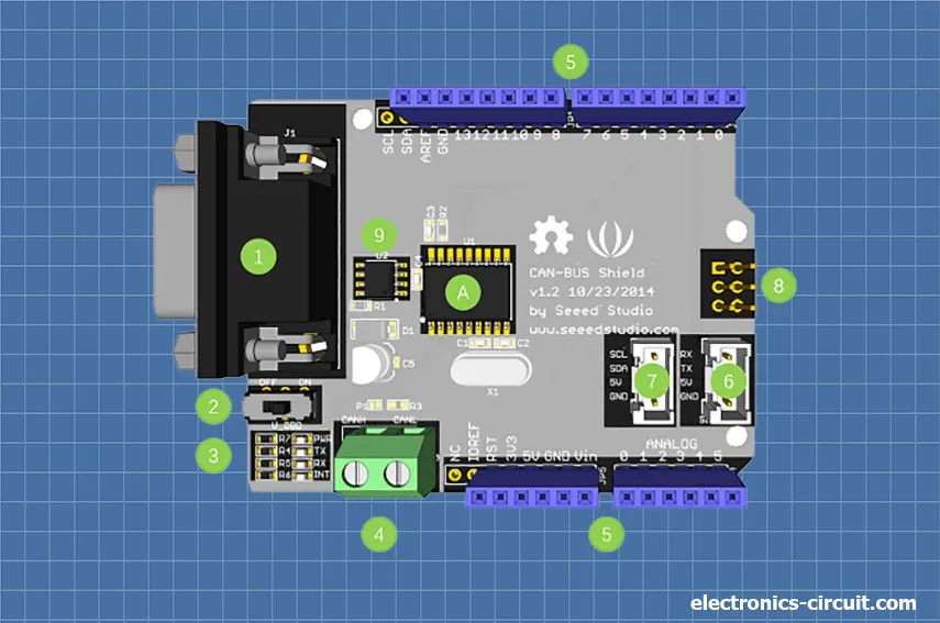
Hardware Overview
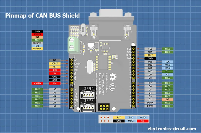
PIN Map
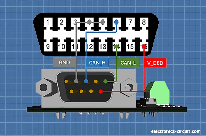
DB9&OBDii Interface
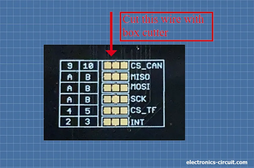
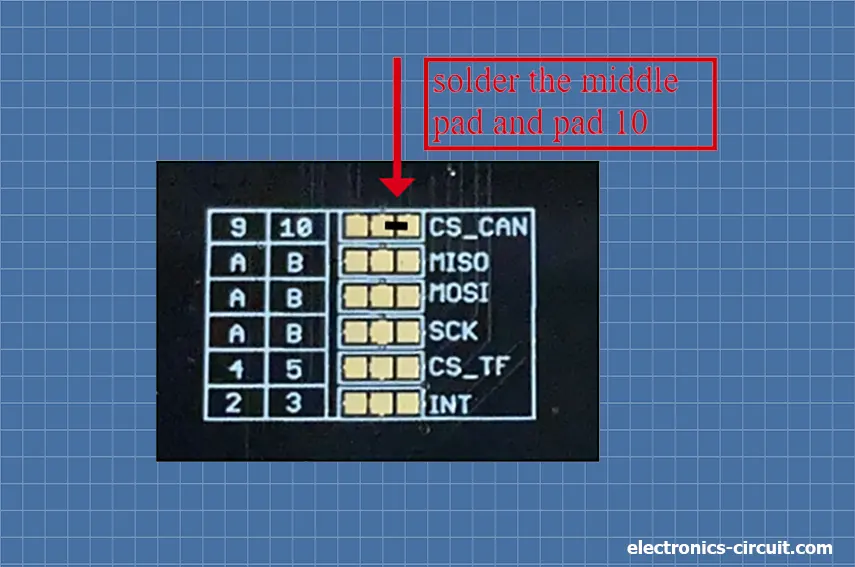
CS pin
The SPI_CS pin of V1.2 is connected to D9 by default. If you want to change to D10, please follow the steps below.
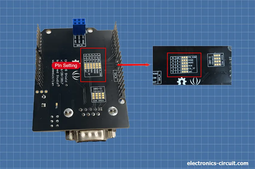
SPI pins
The SPI pins (SCK, MISO, and MOSI) are routed to the ICSP pins by default. Some boards, however, have the SPI pins at D11–D13. If this happens, the PCBA needs to be changed. Look at the back of the PCBA. There are three pads marked MOSI, MISO, and SCK. By default, they are all linked to A. You can switch them to B if you want to.
Note:
For Arduino UNO, Arduino Leonardo, Arduino Mega, and any other Arduino board built on AVR, it works well with the default settings.
Applications of CAN-BUS Shield V2
Limitations of ARDUINO CAN BUS Shield V2.0
Conclusion
The ARDUINO CAN BUS Shield V2.0 is a helpful tool for those familiar with CAN bus systems and with the technical knowledge to set them up properly. While it may not be as reliable as professional diagnostic tools, it is a cost-effective solution for those who need to interface with a vehicle's CAN bus system. It is essential to consider its limitations and use them with caution to ensure accurate and reliable communication and data transfer.


